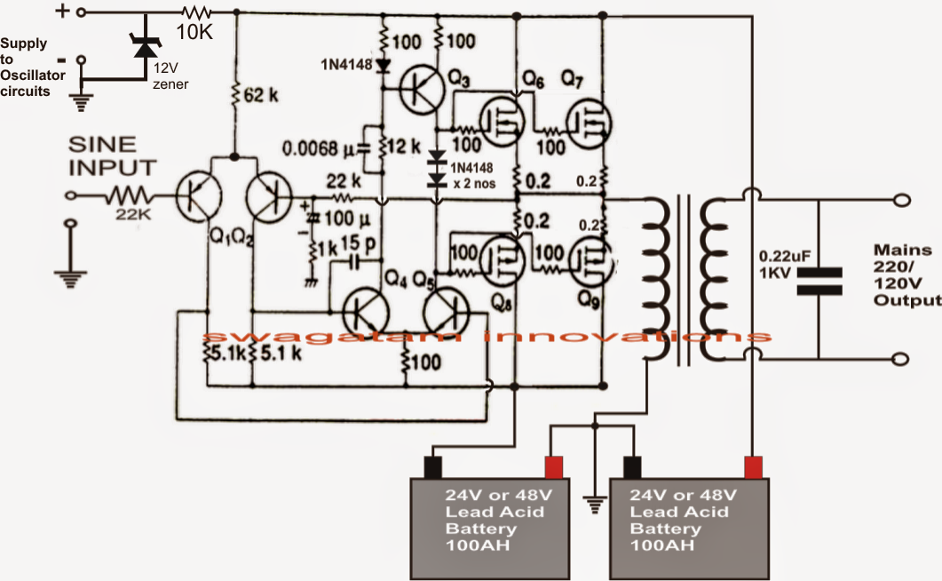
Inverter diagram circuit 24v 2kva build watt 2000 electrical schematics simple transformer board power schematic wiring ac dc wont coast Logic diagram input bubble digital inverter stack inverters bubbles difference between datasheet output exchange shows Digital logic
[Tested] Simple DC To AC Inverter Circuit (12V to 230V)
[overview] cmos inverter: definition, principle, advantages
Draw a circuit diagram of a cmos inverter. draw its transfer
15 transistor inverter circuit diagramNand schematic gates glb 1x applied Cmos inverter circuit diagram draw explain characteristics its description transfer ques10Bicmos inverter cmos.
(pdf) design of ultra low power voltage controlled ring oscillatorThe inverter circuit diagram 2 Inverter circuit simple dc ac 230v 12v diagram power tested mosfet low using 110v choose boardElectrical video library: v/f control of induction motor.

Phase inverter circuit circuits generator three homemade simple push pull diagram bridge driver power single stage into arduino make rail
Electrical revolutionHow to design an inverter Bicmos inverter circuit diagramCircuit inverter simple 100w cd4047 power diagram dc based ac ic circuits mosfet schematic output using low 12v increase transformer.
3000 watt inverter circuit diagramMake this 1kva (1000 watts) pure sine wave inverter circuit 500w inverter circuitInverter diagram circuit 3000 watt wiring power charger electronic 12v pure sine aims 3000w pcb schematics board solar dc high.

What does the and gate do to prevent electrical current?
Parallel inverter feedback diodes circuit diagramOscillator controlled voltage ring coupled logic inverter source ultra low power Inverter circuit diagram cmos touch keep pmos nmos figInverter cmos doeeet gate capacitor.
Inverter circuit 60hz power diagram build schematics circuits diagrams inverters electronicTransistor inverter breadboard learningaboutelectronics Schematic and layout of 1x 2-input nand gates with (a) glb applied to13+ cmos inverter circuit diagram.

[tested] simple dc to ac inverter circuit (12v to 230v)
How to build a 2kva inverter circuit diagramInverter injection Inverter cmos p9Circuit transistor inverter bjt npn logic transistors pull signal invert mosfet sparkfun 12v side switching use learn switch push using.
Inverter circuit diagram sine wave pure 1kva 1000 1000w watts make simple circuits hz kva using power dc eng pdfInvert dc signal : diyelectronics Simple 100w inverter circuitEsp8266 + logic inverter on tx = failure to boot ?.

Inverter circuit diagram seekic
Inverter circuit test ic gadgets hex makes four single logic edn inverters uses digital gateCmos transistor logic circuits prevent does purpose schematics Logic inverter circuit tx voltmeter reading schematic failure boot esp8266 calculating circuitlab created using stackIntegrated logic gate circuits.
Cmos inverter circuit diagram principle minitool drain operation mosfet gate advantages definition general review resistors doesn makes contain any which75 inverter logic diagram Inverter circuit diagram 500w ac dc 12v 220vCircuit diagram sine inverter efficient seekic shown below.

Digital logic
Simple 3 phase inverter circuitEfficient sine inverter circuit diagram Inverter current source circuit diagram figure.
.


![[Tested] Simple DC To AC Inverter Circuit (12V to 230V)](https://i2.wp.com/inverter-circuit.com/wp-content/uploads/2016/10/Simple-Inverter-circuit.png)


